Design D Flip Flop Using Nand Gates
In this tutorial, we will discuss about one of the basic circuits in Digital Electronics knows as the SR Flip Flop. We will see the basic circuit of an SR Flip-Flop using NOR and NAND Gates, its working, truth tables, Clocked SR Flip-Flop and also a simple real-time application.
Introduction
The circuits we have seen till now i.e., the Multiplexers, Demultiplexers, Encoders, Decoders, Parity Generators and Checkers and so on are known as Combinational Logic Circuits. In these types of circuits, the output is dependent only on the current state of the input and it doesn't depend on the past state of inputs or outputs.
Except for a small propagation delay, the output of a Combinational Logic Circuit changes immediately when there is a change in the input.
There are another class of circuits where the output not only depends on the present input, but also on the past inputs / outputs. These types of circuits are known as Sequential Logic Circuits. How can we get the "past input / output" data? We have to have some kind of "memory" to be able to store the data for later use. The devices or circuits which can store data and act as a "memory" unit are known as Latches or Flip-Flops.
NOTE: The terms "latch" and "flip-flop" will be used synonymously, although technically they are slightly different. To put the difference in simple terms, a flip-flop is a clock-controlled latch i.e., the output changes only when there is a clock signal (a HIGH or LOW level, depending on the design).
What is a Flip-Flop?
A Flip-Flop is a basic memory unit which can store 1-bit of digital information. It is a Bistable Electronic Circuit i.e., it has two stable states: HIGH or LOW. As a flip-flop is a bistable element, its output remains in either of the stable states until an external event (known as a trigger) is applied.
Since it retains the output long after the input is applied (unless something is done to change it), a Flip-Flop can be considered as Memory Device, which can store one binary bit.
A simple flip-flop can be designed using two Inverters in series with a feedback from output of second inverter to the input of first inverter. The following circuits shows the flip-flop using inverters.

Let Q1 be the input and Q3 be the output. Initially, assume the feedback is disconnected and Q1 is made 0 (Logic 0, LOW, bit 0) by connecting it to ground. The Q3 will also be 0. Now, if the feedback is connected and the input Q1 is disconnected from ground, the Q3 will still continue to be at 0.

Similarly, instead of ground, if we repeat the same process with 1 (Logic 1, HIGH, bit 1), the output Q3 stays at 1.

This is a simple flip-flop with two stable states and it remains in a particular state, hence a memory, until there is an external event (like change in input in this, case).
Overview of SR Flip Flop
The above inverter-based flip-flop is just for understanding the working but it doesn't have any practical uses as there is no provision for applying any inputs. This is where NOR and NAND Gates come into picture. The above inverter-based flip-flop can be implemented using a NOR gate as shown below.

Ignore the 'R' and 'S' values for now and let us redraw the above circuit in a more conventional form and rename Q2 as Q and Q3 as Q.
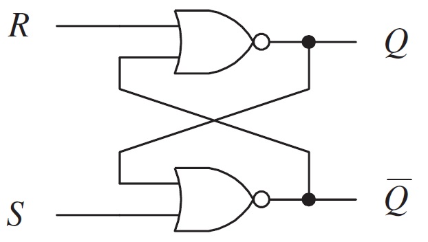
From this, the flip-flop has two inputs: R and S and two outputs: Q and Q and it is clear from the representation that the outputs are complementary to each other. Let us try to analyze the different possibilities of inputs and their corresponding outputs.
An important point to note here is that for a NOR gate, Logic '1' is a dominating input and if any one of its input is Logic '1' (HIGH), then the output is Logic '0' (LOW), irrespective of the other input. With this in mind, let us analyze the above circuit.
Case 1: R = 0 and S = 0
In the first case, the inputs of both the NOR gates are Logic '0'. As neither of them are dominating inputs, they have no effect on the output. So, the output retains their previous states i.e., there is no change in the output. This condition is called as Hold Condition or No Change Condition.
Case 2: R = 0 and S = 1
In this case, the 'S' input is 1, which means the output of the NOR Gate B will become 0. As a result, both the inputs of NOR Gate A become 0 and hence the output of the NOR Gate A and thus the value of Q is 1 (HIGH). As '1' at input S makes the output to switch to one of its stable states and sets it to '1', the S input is known as SET input.
Case 3: R = 1 and S = 0
In this case, the 'R' input is 1, which means the output of the NOR Gate A will become 0 i.e., Q is 0 (LOW). As a result, both the inputs of NOR Gate B become 0 and hence the output of the NOR Gate B is 1 (HIGH). As '1' at input R makes the output to switch to one of its stable states and resets it to '0', the R input is known as RESET input.
Case 4: R = 1 and S = 1
This input condition is forbidden as it forces outputs of both NOR Gates to become 0, which is a violation of complementary outputs. Even if this input condition is applied, if the next inputs become R = 0 and S = 0 (hold condition), then it causes a 'race condition' between the NOR Gates, which causes an unstable or unpredictable state at the output.
Hence, the input condition R = 1 and S = 1 is simply not used.
So, based on the above-mentioned cases and different combinations of inputs, the truth table for SR Flip-Flop is shown in the following table.
| R | S | Q | State |
| 0 | 0 | Last State | No Change |
| 0 | 1 | 1 | Set |
| 1 | 0 | 0 | Reset |
| 1 | 1 | Not Applied (?) | Forbidden |
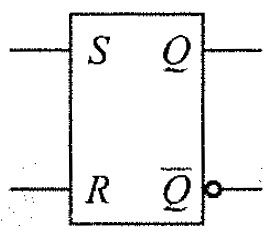
The logic symbol of an SR Flip-Flop is shown below:
SR Flip-Flop using NAND Gates (Technically, RS Flip-Flop)
An SR flip flop can also be designed by cross coupling of two NAND gates, but the Hold and Forbidden states are reversed. It is an active low input SR flip – flop and hence let us call it RS Flip-Flop. The circuit of SR flip – flop using NAND gates is shown in below figure
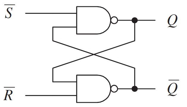
An important point about NAND gate is that its dominating input is 0 i.e., if any of its input is Logic '0', the output is Logic '1', irrespective of the other input. The output is 0, only if all the inputs are 1. With this in mind, let us see the working of a NAND based RS Flip-Flop.
Case 1: R = 1 and S = 1
When both the S and R inputs are HIGH, the output remains in previous state i.e., it holds the previous data.
Case 2: R = 1 and S = 0
When R input is HIGH and S input is LOW, the flip flop will be in SET state. As R is HIGH, the output of NAND gate B i.e., Q becomes LOW. This causes both the inputs of NAND gate A to become LOW and hence, the output of NAND gate A i.e., Q becomes HIGH.
Case 3: R = 0 and S = 1
When R input is LOW and S input is HIGH, the flip flop will be in RESET state. As S is HIGH, the output of NAND gate A i.e., Q becomes LOW. This causes both the inputs of NAND gate B to become LOW and hence, the output of NAND gate A i.e., Q becomes HIGH.
Case 3: R = 0 and S = 0
When both the R and S inputs are LOW, the flip flop will be in undefined state. Because the low inputs of S and R, violates the rule of flip – flop that the outputs should complement to each other. So, the flip flop is in undefined state (or forbidden state).
The truth table below summarizes the above explained working of SR Flip Flop designed with the help of a NAND gates.
| R | S | Q | State |
| 1 | 1 | Last State | No Change |
| 1 | 0 | 1 | Set |
| 0 | 1 | 0 | Reset |
| 0 | 0 | Not Applied (?) | Forbidden |
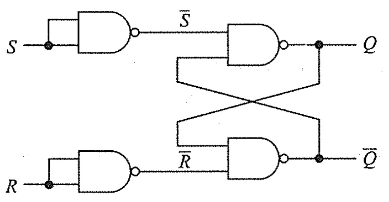
The RS Flip-Flop using NAND gates can be converted to have a same truth table as a regular SR Flip-Flip by inverting the inputs. Instead of using inverters, we can use NAND gates with common input as shown in the following figure.
The problem with simple SR flip – flops is that they are level sensitive to the control signal (although not shown in figure) which makes them a transparent device. In order to avoid this, Gated or Clocked SR flip – flops are introduced (whenever the term SR flip – flop is used, it usually refers to clocked SR flip – flop). Clock signal makes the device edge sensitive (and hence no transparency).
Clocked SR Flip – Flops
Two types of clocked SR flip – flops are possible: based on NAND and based on NOR. The circuit of clocked SR flip – flop using NAND gates is shown below
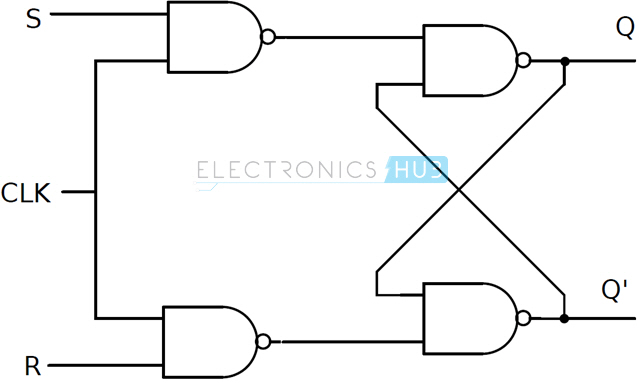
This circuit is formed by adding two NAND gates to NAND based SR flip – flop. The inputs are active high as the extra NAND gate inverts the inputs. A clock pulse is given as input to both the extra NAND gates.
Hence the transition of the clock pulse is a key factor in functioning if this device. Assuming it is a positive edge triggered device, the truth table for this flip – flop is shown below.
| Clock | R | S | Q | State |
| ↓ or 0 or 1 | X | X | Last State | No Change (Hold) |
| ↑ | 0 | 0 | Last State | No Change (Hold) |
| ↑ | 0 | 1 | 1 | Set |
| ↑ | 1 | 0 | 0 | Reset |
| ↑ | 1 | 1 | Not Applied (?) | Forbidden |
The same can be achieved by using NOR gates. The circuit of clocked SR flip – flop using NOR gates is shown below.
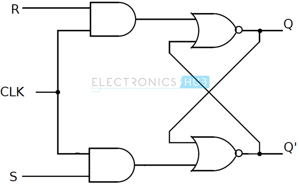
The figure suggests a structure of RS flip – flop (as R is associated to the output Q), the functionality of SET and RESET remain the same i.e., when S is high, Q is set to 1 and when R is high, Q is reset to 0.
Applications
SR flip – flops are very simple circuits but are not widely used in practical circuits because of their illegal state, where both S and R are high (S = R = 1). But they are used in switching circuits as they provide simple switching function (between Set and Reset).
One such application is a Switch de-bounce circuit. The SR flip-flops are used to eliminate mechanical bounce of switches in digital circuits.
Mechanical Bounce
Mechanical switches, when pressed or released, often take some time and vibrate several times before settling down. This non–ideal behavior of the switch is called as Switch Bounce or Mechanical Bounce. This mechanical bounce will tend to fluctuate between low and high voltages, which can be interpreted by digital circuit.
This can result in variation of pulse signals and these series of unwanted pulses will result in the digital system to work incorrectly.

For example, in this bouncing period of the signal, the fluctuations in the output voltage are very high and therefore the register counts several inputs instead of single input. To eliminate this kind of behavior of digital circuits, we use Switch Debouncing Circuits and in this case, using SR flip–flops.
How does SR Flip-Flop Eliminate the Mechanical Bounce?
Based on the present state output, if the set or reset buttons are depressed then the output will change in a manner that it counts more than one signal input i.e., the circuit may receive some unwanted pulse signals and thus because of the mechanical bouncing action of machines, there is no change in outputs at Q.
When the button is pressed, the contact will affect the flip-flop's input and there will be change in the present state and no further effects on the circuit/machine for any other mechanical switch bounces. If there is any additional input from the switch, there will be no change and SR flip – flop will reset after some small period of time.
So, the same switch will come to use only after an SR flip – flop executes a state change i.e., only after receiving the single clock pulse signal.
The circuit of a switch de–bouncing circuit is shown below.
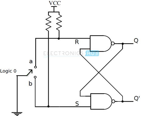
The input to the switch is connected to ground (logic 0). There are two pull up resistors connected to each of the input. They ensure that flip – flop inputs S and R are always 1 when the switch is between contacts.
Another circuit can be constructed with NOR SR flip – flop.
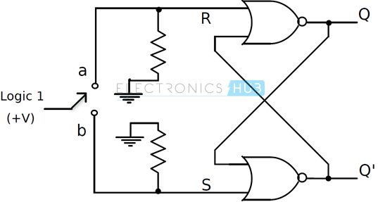
The input to the switch is connected to logic 1. There are two pull down resistors connected to each of the input. They ensure that flip – flop inputs S and R are always 0 when the switch is between the contacts a and b.
Commonly used ICs for eliminating the mechanical switch bounce are MAX6816 – single input, MAX6817 – dual input, MAX6818 – octal input switch de-bouncer ICs. These ICs contain the necessary configuration with the SR flip – flops.
Conclusion
A complete beginner's tutorial on the basic memory circuit known as the SR Latch or the SR Flip-Flop. You learned what is an SR Flip-Flop, its working, its implementation using NOR and NAND Gates, clocked Sr flip flop and also an important application of SR flip-flop.
Design D Flip Flop Using Nand Gates
Source: https://www.electronicshub.org/sr-flip-flop-design-with-nor-and-nand-logic-gates/
0 Response to "Design D Flip Flop Using Nand Gates"
Post a Comment